Topic outline
- Information Systems Modelling (IFS2103)
Information Systems Modelling (IFS2103)
Welcome to Information Systems Modeling
This course introduces you to modelling of electronic systems. The system models are important because they aid the programmers to design software that are suitable in each context.
Information Systems is an academic study of systems with a specific reference to information and the complementary networks of hardware and software that people and organizations use to collect, filter, process, create and also distribute data.
Models of both new and existing system are used during requirements engineering. Models of the existing systems help clarify what the existing system does and can be used as a basis for discussing its strengths and weaknesses. These then lead to requirements for the new system.
Content
1: Introduction to Information Systems Modelling
2: Explain the relevance of information systems in an organization
3. Introduction to modelling – System Models: Why model?:
Subtopics -
- Data Design Concepts
- DBMS Components
- What is the relationship between data, design and modelling?
- Entity-Relationship Diagrams
- Normalisation
4. Object Modeling
Subtopics
How are objects useful in modelling?
State Transition Diagrams
Activity Diagrams
CASE Tools
5. System ArchitectureSubtopics- Designing a system considers people interests and available computer resources
- Elements of an Architecture
- Creating an Architecture Design
- Hardware and Software Specification
Lecturer: Prof. Zake (0788485749)
- Data Design Concepts
- Online Lectures
- Assessments - Tests and Assignments
Assessments - Tests and Assignments
Your assessment - make sure you attempt every assessment.
- Submit by the 7th February 2023
- CAT 1 TEST. 13 March 4 pm - 15th March 2023 12.00 Noon Quiz
NOTE:
- This is your Test 1.
- Answer ALL questions.
- The Test lasts 1 hour (60 Minutes).
- You cannot re-open the test once you start.
- The Test is out of 20
1. How are Information Systems used in business and social collaboration? (4 Marks)
2. What systems are used to link different ports? (4 Marks)
3. Identify Three (3) hierarchies of IS users and types of systems they use (6 Marks)
4. What are the key activities of IS and how does the environment impact those activities?
(6 Marks)
- Topic 2: Fundamentals of Information Systems 1
Topic 2: Fundamentals of Information Systems 1
Objectives
•Define information system and name seven types of information system applications.•Identify different types of stakeholders who use or develop information systems, and give examples of each.•Define the unique role of systems analysts in the development of information systems.•Identify those skills needed to successfully function as an information system analyst.•Describe current business drivers that influence information systems development.•Describe current technology drivers that influence information systems development.Introduces terms in IFS
- A modeling language is any artificial language that can be used to express information or knowledge or systems in a structure that is defined by a consistent set of rules. The rules are used for interpretation of the meaning of components in the structure.A modeling language can be graphical or textual.Graphical modeling languages use a diagram technique with named symbols that represent concepts and lines that connect the symbols and represent relationships and various other graphical notation to represent constraints.Textual modeling languages may use standardized keywords accompanied by parameters or natural language terms and phrases to make computer-interpretable expressions.
- Topic 1: Introduction to Information Systems Modeling
Topic 1: Introduction to Information Systems Modeling
This PowerPoint outlines the differences between Data, Information and Knowledge.
This presentation explains why models are necessary and gives examples.
- Topic 3: Problem Solving in Information Systems
Topic 3: Problem Solving in Information Systems
Objectives
•To introduce the nature of problems•To introduce examples of typical problems found in Information systems•To introduce a range of problem solving approaches or strategiesProcesses towards solving problems for Information Systems Modeling.
Example: Building A New Ordering System for a cookie selling business

- Topic 4: UML Diagrams
Topic 4: UML Diagrams
What is a UML Diagram?
UML is a way of visualizing a software program using a collection of diagrams. The notation has evolved from the work of Grady Booch, James Rumbaugh, Ivar Jacobson, and the Rational Software Corporation to be used for object-oriented design, but it has since been extended to cover a wider variety of software engineering projects. Today, UML is accepted by the Object Management Group (OMG) as the standard for modeling software development.
Types of UML Diagrams
The current UML standards call for 13 different types of diagrams: class, activity, object, use case, sequence, package, state, component, communication, composite structure, interaction overview, timing, and deployment.
These diagrams are organized into two distinct groups: structural diagrams and behavioral or interaction diagrams.
Structural UML diagrams
- Class diagram
- Package diagram
- Object diagram
- Component diagram
- Composite structure diagram
- Deployment diagram
Behavioral UML diagrams
- Activity diagram
- Sequence diagram
- Use case diagram
- State diagram
- Communication diagram
- Interaction overview diagram
- Timing diagram
Class Diagram
Class diagrams are the backbone of almost every object-oriented method, including UML. They describe the static structure of a system. Learn moreWatch this short video about UML Class Diagrams
Package Diagram
Package diagrams are a subset of class diagrams, but developers sometimes treat them as a separate technique. Package diagrams organize elements of a system into related groups to minimize dependencies between packages.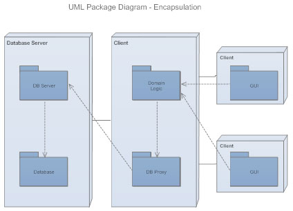
Object Diagram
Object diagrams describe the static structure of a system at a particular time. They can be used to test class diagrams for accuracy.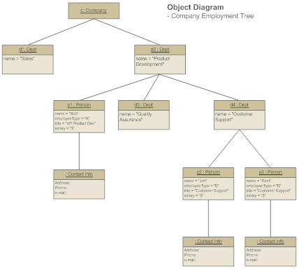
https://youtu.be/6Jk9fvLRWJ0
Composite Structure Diagram
Composite structure diagrams show the internal part of a class.Use Case Diagram
Use case diagrams model the functionality of a system using actors and use cases. Learn more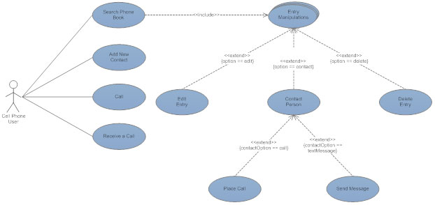
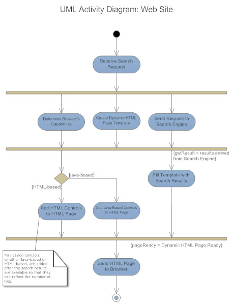
Activity diagrams illustrate the dynamic nature of a system by modeling the flow of control from activity to activity. An activity represents an operation on some class in the system that results in a change in the state of the system. Typically, activity diagrams are used to model workflow or business processes and internal operation. Learn more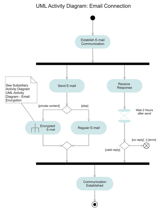
Sequence Diagram
Sequence diagrams describe interactions among classes in terms of an exchange of messages over time. Learn more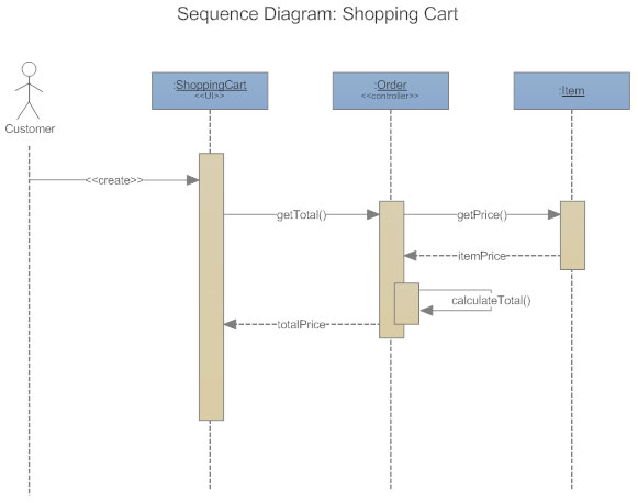
Interaction Overview Diagram
Interaction overview diagrams are a combination of activity and sequence diagrams. They model a sequence of actions and let you deconstruct more complex interactions into manageable occurrences. You should use the same notation on interaction overview diagrams that you would see on an activity diagram.Timing Diagram
A timing diagram is a type of behavioral or interaction UML diagram that focuses on processes that take place during a specific period of time. They're a special instance of a sequence diagram, except time is shown to increase from left to right instead of top down.Communication Diagram
Communication diagrams model the interactions between objects in sequence. They describe both the static structure and the dynamic behavior of a system. In many ways, a communication diagram is a simplified version of a collaboration diagram introduced in UML 2.0.State Diagram
Statechart diagrams, now known as state machine diagrams and state diagrams describe the dynamic behavior of a system in response to external stimuli. State diagrams are especially useful in modeling reactive objects whose states are triggered by specific events. Learn more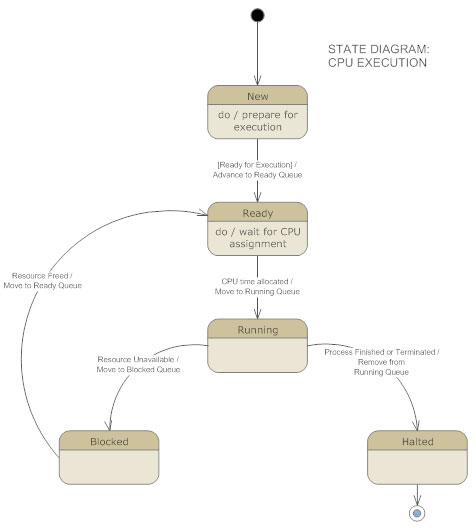
Component Diagram
Component diagrams describe the organization of physical software components, including source code, run-time (binary) code, and executables. Learn more.
Deployment Diagram
Deployment diagrams depict the physical resources in a system, including nodes, components, and connections.Check the examples of Class UML Diagrams and draw your own.
- •Activity diagrams describe the workflow behavior and parallel processing in a system, i.e. process flows in the system are captured in the activity diagram•Activity diagrams are the object-oriented equivalent of flow charts and data-flow diagrams from structured development•Activity diagram illustrates the dynamic nature of a system by modeling the flow of control from activity to activity
- Process model: diagrams how data flows through the system
- Data model: diagrams the relationships between data files
- Uses cases are drawn to capture the system's functional requirements from the users' perspectiveFunctional requirements capture the intended behavior of the system. This behavior may be expressed as;services,tasks orfunctions the system is required to perform.A use case defines a goal-oriented set of interactions between external actors and the system under consideration.
Explanation of Object-Oriented processes.
Explanation.